Heat exchanger temperature control is common to all process industries. However, many temperature control loops have a difficult time maintaining setpoint. The controller performance is excellent at normal plant rates, but is unacceptable at lower rates for plant startup. Sometimes the temperature control loop sees frequent visits from the Control Engineer for re-tuning, or perhaps the Operations team has placed the controller in MANUAL because “it never worked from day one” or “only an Operator is robust enough to manage this control loop.”
Have you ever wondered why such a simple control loop can be so difficult to work with? Are you ready to try yet another home-cooked control strategy, hoping it does not fail like the last dozen? One common reason for such poor behaviour lies with the hydraulic behaviour of a control valve that is in series with another resistance.
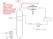
We will consider the temperature control loop below.
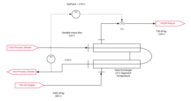
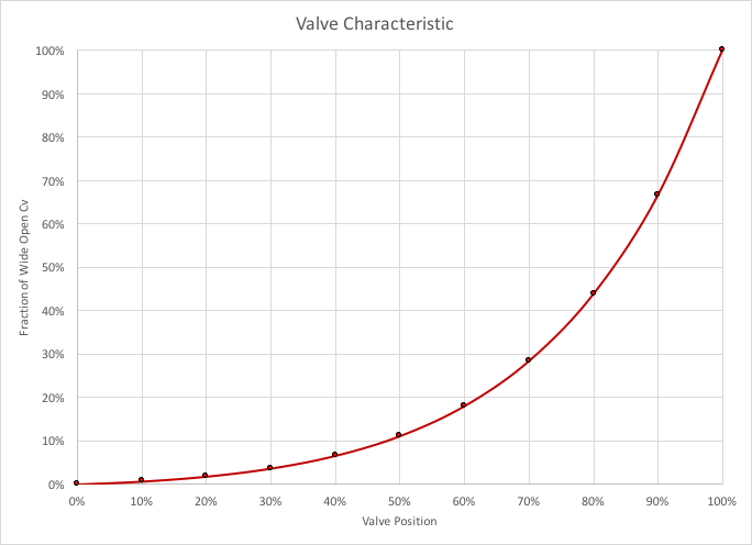
A process stream (SG = 1, Cp = 4 kJ/kg K) is heated from the feed temperature of 120 C to the setpoint of 170 C. Hot oil (SG = 1, Cp = 4 kJ/kg K) at 300 C is the source of heat, with the supply pressure at 1000 kPag and the return header at 700 kPag. The heat exchanger was designed for an approach temperature of 10 C at the normal operating process flow rate of 100,000 kg/h. The heat exchanger takes 200 kPa at this rate. An equal percent control valve is size to be 60% open at the normal operating conditions: this requires a control valve with Cv = 82. The trim characteristic is shown below. At normal conditions, the valve is required to pass 29,400 kg/h of hot oil. Startup is at 20% turndown, and we require 5,882 kg/h.
First, we determine the relationship for the hot oil flow rate as a function of control valve position. This is the familiar problem of two resistances in series. If this were an electrical problem, the relationship between voltage, current and resistance is
V = I R
Hydraulics obeys a quadratic relationship.
DP = Q^2 / Cv^2
Rather than resistance, valve friction is expressed as a conductivity, the valve coefficient.
For the electrical resistance in series we use
V = I (R1 + R2)
And for our quadratic hydraulic relation we have
DP = Q^2 (1/Cv1^2 + 1/Cv2^2)
The pressure drop between the hot oil supply and return is fixed at 300 kPa. The equivalent conductivity of the heat exchanger can be determined from a datasheet that provides the actual pressure drop at a given flow rate.
Start by choosing flow rate of hot oil, say 1,500 kg/h. Calculate the pressure drop through the exchanger at this flow rate. The left-over pressure drop and the hot oil flow rate determines the required valve coefficient, and this determines the valve position.
Over the range of valve positions we obtain a graph for the hot oil flow rate.
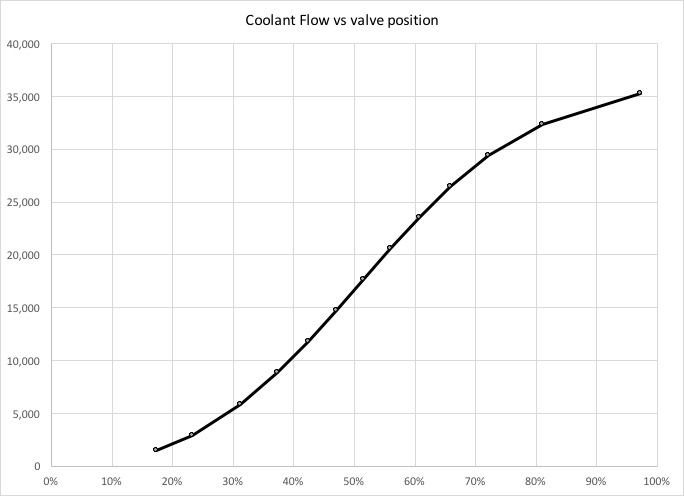
The trend is quite linear over the range of valve positions of interest: normal operation at 60%, and startup at about 35%. This is excellent.
Or, is it?
Part 2 will look at how this hydraulic behaviour translates into control problems for the heat exchanger.