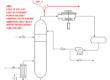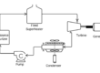
In Part 1, we saw that the hot oil flow rate through the heat exchanger was nearly linear with valve position. Our experience with the exchanger is that the one set of PID tuning parameters is wonderful at one operating point, but fails at another.
Why?
Good control requires repeatable performance from the PID algorithm over the full range of operating conditions. This means that a 1% increase in valve position provides the same increase in the process temperature. This is the Process Gain.
Kp = dT/dx = fairly constant
So how does the process gain change with valve position? The answer to this requires some fairly tedious calculations. First we determine the control valve position (and hot oil flow rate) for a given process flow rate. Then, we find the hot oil flow rate (and the process outlet temperature) where the valve position is increased by 1%. We are left with the increase in process temperature for a 1% increase in valve position. The process gain for our example is left as an exercise for the reader.
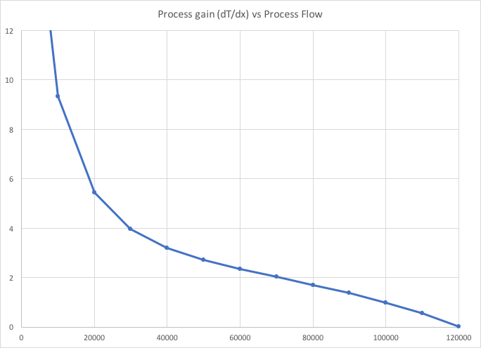
What are the implications for our PID controller where the process gain at startup is 4 times the value at the normal operating conditions?
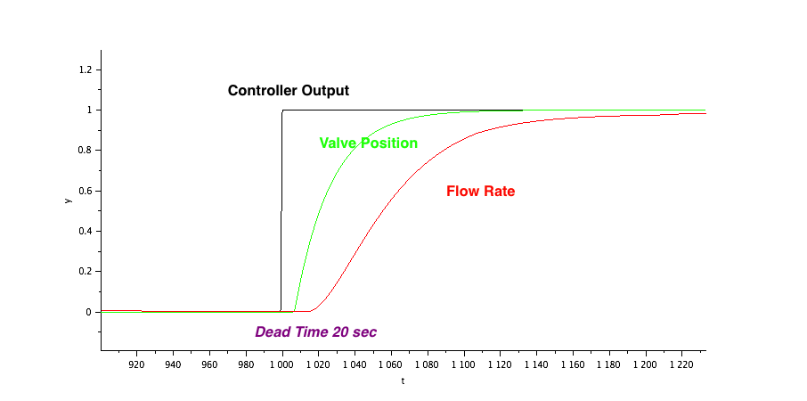
Let’s assume that the process is described by a First Order Plus Dead Time model with a dead time of 20 seconds and a process time constant of 60 seconds.
Now we pick one of two strategies for tuning a PID controller (Kevin’s Whiteboard: Tuning Strategies):
1. As fast as possible,
2. Manage the upset in a specified length of time.
I prefer to tune controllers to manage the upset in a specified length of time because I can make a conscious tradeoff between performance and smooth action with the controller output. In this case, I chose a response time of 40 seconds. For a PI controller, the tuning constants that are applicable at the normal operating conditions are K = 1, TI = 60 sec.
The closed loop response to a setpoint change and disturbance at the normal operating conditions is:
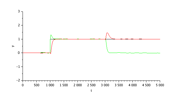
This is pretty good. There is a bit of overshoot on the valve position (green), but the temperature response is smooth.
If we reduce the process flow rate to 1/2, then the process gain will increase by a factor of 2.7. The process response time and time delay increase by a factor of 2. With no change to the PID tuning, the response to the setpoint change and disturbance is:
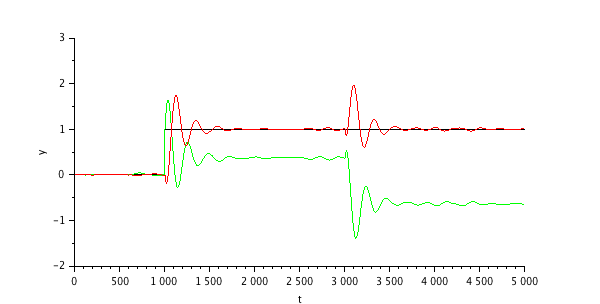
This is not looking good. There are a lot of oscillations as the process responds to the setpoint change and the disturbance. Now we have some oscillations in the process temperature. At the startup flow rate of 1/3 normal, the process gain has increased by a factor of 3.5, and the time delay and process response time have both increased by a factor of 3.
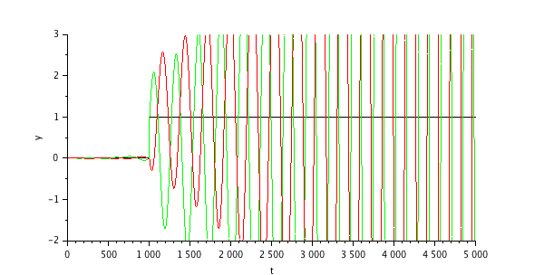
The controller is unstable. The combination of the extremely sensitve process (small increase in valve position produces a very large change in temperature) and the the dead time of 60 seconds makes this choice of tuning parameters unusable. The controller is simply too aggressive for this applicaiton.
The simplest solution is for the operator to leave the controller in MANUAL and make slow, incremental changes to the control valve. This increases the workload on the operator, decreases the energy efficiency of the process and potentially causes quality control problems.
We need a better behaved process, or a controller that can accoomdate the change in process behaviour.
Part 3 describes how to make the process behave better.