
Pipeline supply pumps must meet an interesting set of operating conditions. The flow rate is generally low and the required discharge pressure is high. This requires either a small multistage centrifugal pump or a positive displacement pump, such as a plunger pump. A plunger pump with a VFD is quite suitable for delivering fluid to a pipeline. However, how do we predict the pressure pulsations from pump, and how do we predict how the pressure waves travel down the pipeline?
Before we get to the difficult task of modelling pressure waves caused by a plunger pump, let’s consider the simpler problem of steady flow through the pipeline, followed by a sudden closure of a valve.
This is the classic water hammer problem, which was analyzed by the Russian mathematician Zhukovsky in 1898. The general formula for the pressure rise caused by a rapid change in the fluid velocity is:
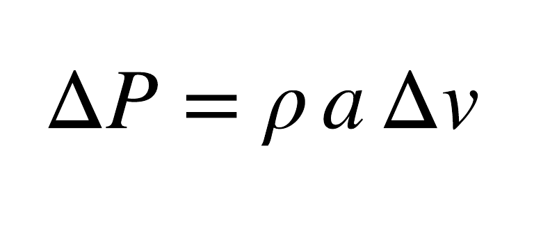
Where a is the speed of sound and \rho is the fluid density. This is visualized below where the valve is closed and the shock wave travels up the pipeline.
The magnitude of the shock wave decreases as the wave travels up the pipeline because the downstream fluid is compressible: the compression of the long fluid column allows the velocity downstream side of the shock to increase. The shock would disappear in a longer pipeline.
A plunger pump produces rapid changes in flow rate (velocity), so it begs the question “what do the pulsations look like?”
First, we need to look at the cyclic variation in flow rate for plunger pumps. The flow rate variation for simplex, duplex and triplex pumps is shown below.
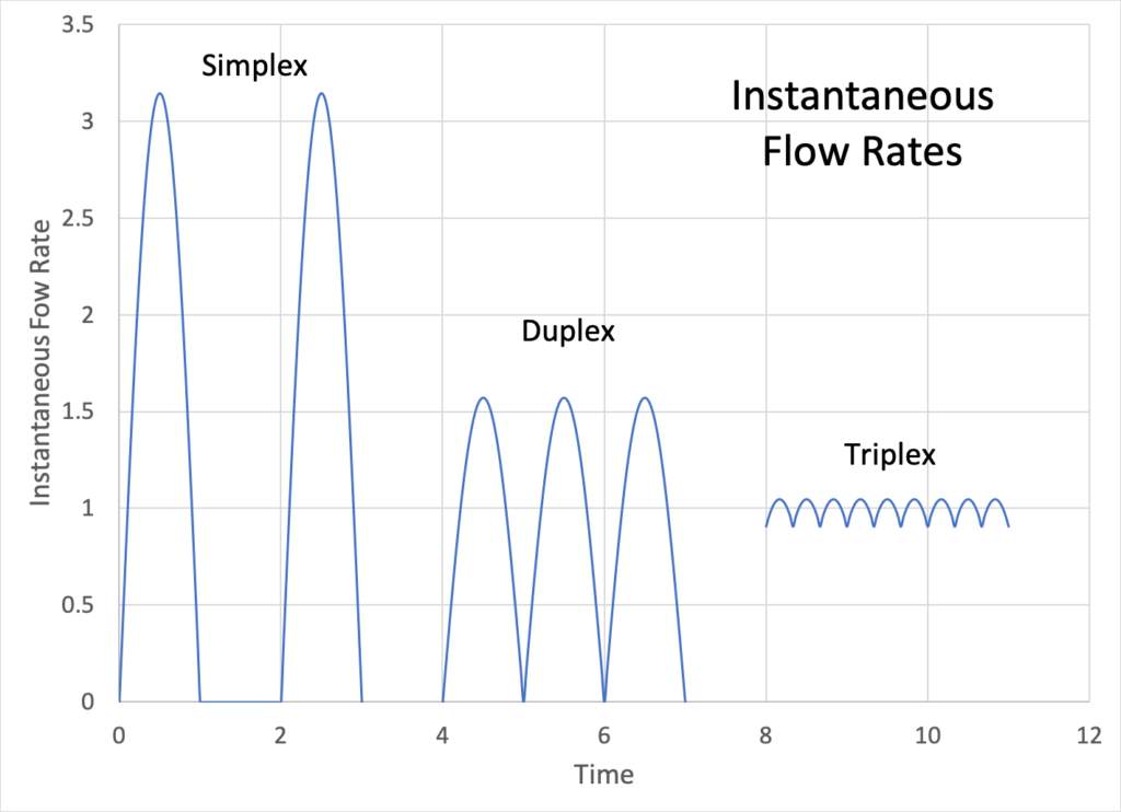
Simplex pumps have the largest variation in flow rate, and triplex have the least. The peak:average and minimum:average flow rates are tabulated below.

The Method of Characteristics, as presented by Wylie and Streeter, is well suited to predicting the movement of pressure pulsations along the pipeline. The reader will be spared the mathematical details of the simulation method and referred to the text (Chapters two and three) for reference.
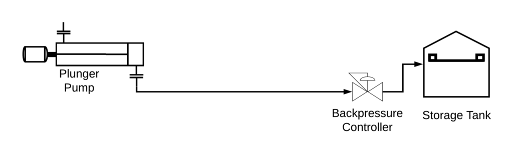
In this example we will consider a pump that delivers an average flow rate of 100 m3/h to a 150 mm ID pipeline. The pipeline is 20 km long. The back pressure on the pipeline is controlled at 1000 kPa with a control valve, and the fluid is delivered to a storage tank. The fluid density is 1000 kg/m3 and the speed of sound is 1000 m/s.
The simulation results for simplex, duplex and triplex pumps follow. In all cases the pressure profile begins with the steady state mean velocity. The plunger pump then creates the cyclic variations in flow rate.
The simplex pump causes large pulsations. Period. Duplex is a bit better. These pumps are common for chemical feed systems but not for pipeline flows. The piping must be designed for much higher flow rates to keep the pressure spikes reasonable. Over-designing chemical feed tubing (say from 1/2” to 3/4”) is much less expensive for a small chemical feed system than a pipeline. Both of these pumps would require large dampeners to reduce pulsations to an acceptable level.
The pulsations from the Triplex pulsations are much lower, which is the reason why triplex pumps are used in pipeline service. The pressure pulsations are largest at the pump discharge, and die out after 10 km. A smaller pulsation dampener is needed to reduce pulsations to an acceptable level.
Dynamic modelling of is used to design a reliable pipeline and plunger pump system. This tool can test different startup procedures for the pump to ensure that the initial pressure surge does not raise the pressure to the MAWP.
References
E.B. Wylie and V.L. Streeter, “Fluid Transients in Systems,” Prentice-Hall (1993).