
Introduction
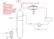
Process engineers are concerned about safety, and we spend a lot of our time considering overpressure protection. A simple example is thermal expansion of a blocked in heat exchanger.
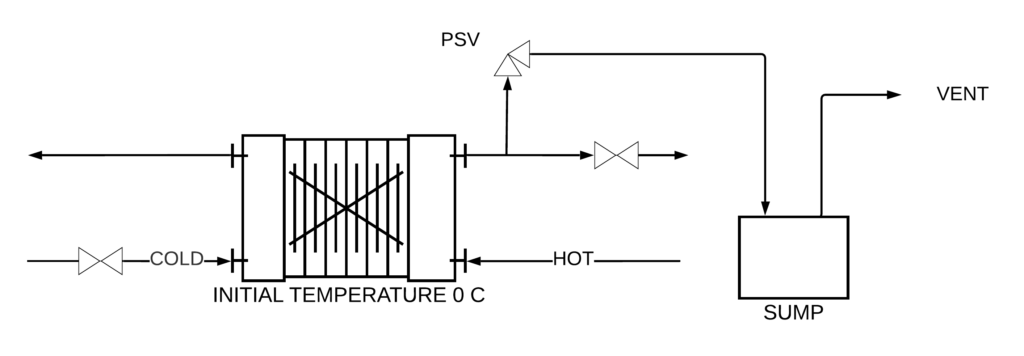
The cold cold side warms up, the cold fluid expands a tiny bit and the exchanger ruptures. The solution is to install a small PSV on the cold side of the exchanger, and this allows a tiny bit of fluid to bleed out. Often, the PSV will discharge to a small, local sump. The expansion flow rate is dictated by the amount of heat that is exchanged, the thermal expansion coefficient and the heat capacity:
m = Q α / Cp
How do we get the amount of heat for the blocked in exchanger? We don’t usually give this overpressure scenario a lot of thought, and follow the guidance given by API 521 (section 4.4.12.3) for the amount of heat Q:
For heat exchangers, this can be taken as the maximum exchanger duty during operation.
API 521 Pressure-relieving and Depressuring Systems, Sixth Edition, January 2014.
But, does this make sense? We are actually rating the performance of the exchanger under abnormal conditions, and we did not use any of the geometric properties of the exchanger: heat transfer area, heat transfer coefficient, the initial cold fluid temperature or the hot fluid temperature. Is this method legitimate?
And what if the fluid could be hot enough to flash? If the sump vent is too small then the backpressure on the sump could exceed the MAWP. If we overestimate the venting rate then we will dismiss a simple design and will need a larger, more complex and possibly more risky design. The sucess of a simple design hinges on having a reasonable estimate for the flashing steam flow rate, and yet to still be conservative because our knowledge is not perfect.
We will walk through an example for determining the liquid relief load for thermal expansion, and we will use different basis for estimating the maximum flow rate of flashing steam.
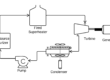
Our Exchanger
Our example will be a plate frame excanger with the following properties.
- Fluid is water
- Area 100 m2
- Design duty 5400 kW
- Design pressure 1500 kPag.
- Plate spacing 8 mm.
- U = 2.5 kW/m2.K at design conditions
- At design operating conditions: hot side temperature 130 to 82 C; cold side temperature 60 to 108 C.
Important fluid properies at the maximum temperature 130 C are tabulated below
- Density 935 kg/m3
- Heat capacity 4.265 kJ/kg.K
- Thermal conductivity 0.684 W/m.K
- Thermal expansion coefficient 0.00091 1/K.
API 521 method
API 521 recommends using the design heat duty to determine the thermal expansion rate.
m = Q α / Cp
In our case, we will be conservative and take the physical properties at the maximum temperature of 130 C, and the calculated relief rate is 4148 kg/h of water. We could use a PSV liquid sizing method to determine the orifice diameter to relieve this flow rate at our MAWP.
API 521 does not say anything about the temperature of the relieving fluid. So, should we assume that the fluid is relieving at this flow rate and is also at the maximum temperature of 130 C? Is this assumption overly conservative?
Our steam tables tell us the enthalpy of liquid water at 130 C, and the enthalpy of saturated steam and water at 100 C. From this, we will get a vapour quality x = 0.0564, and a steam flow rate of 234 kg/h. Now we can determine the backpressure on the sump and check if this is a safe destination for our thermal expansion PSV.
But we did not use any heat transfer properties of the exchanger, or the initial temperature, to determine this relief rate? Is this important?
Let’s look at this in another way.
Second look: Design Heat Transfer Coefficient
Assessing the performance of heat transfer equipment under a different set of conditions requires the heat transfer coefficient and the temperature driving force. Lets see how the heat exchanger performs if we specify the heat transfer coefficient to be at the design value, Uo = 2.5 kW/m2.K. Our standard heat transfer formula is:
Q = U A (TH – TC)
And we will evaluate this from the initial temperature 0 C to the maximum temperature 130 C.
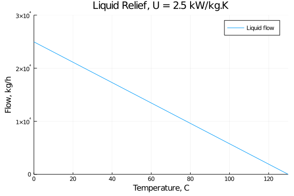
AAHHHHHHGGHGHGHGH. The calculated relief rate at the coldest temperature is 25,000 kg/h, substantially higher than the API 521 calculation of 4148 kg/h. This looks troubling.
Let’s avoid the temptation to question the recommended practice in API 521 (for now), and instead look at the amount of steam that would flash off. Of course, flashing only occurs where the fluid is warmer than 100 C.
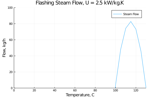
Whew, that is a relief. Our steam flow has a maximum value of about 80 kg/h at 115 C. I will leave it as an exercise for the reader to show that the maximum steam flow will be at the midpoint of 100 C (zero flashing) and the maximum temperature of 130 C (zero relief rate).
But our estimated initial relief rate (at 0 C) is very troubling. Did we miss something?
More detailed look: Governing resistance to heat transfer
The overall heat transfer coefficient (U at design conditions) is a function of the individual heat transfer coefficients on both sides of our plate:
1/UD = 1/ho + 1/hi
This form shows us how the resistance to heat transfer is additive for the two sides of the exchagner.
Under the design conditions, the flow rates on both sides of our exchanger are nearly equal, and the fluid properties (Prandtl number) are also fairly similar. We will assume that the individual heat transfer coefficeints are the same. Thus,
ho = 2 UD
But what is the value for the hi? There is no velocity, and the heat transfer coefficient for forced convection between parallel plates is a strong function of velocity (expressed as Reynolds number). This breaks down for our case of zero velocity and zero Reynolds number.
The plates are only 8 mm apart, and this is spacing is too narrow for meaningful natural convection. The heat transfer process on the cold side is dominated by conduction: the heat transfer coefficient is approximated by
hi = k / (l/2)
where l is the gap between plate. At the maximum temperature of 130 C, the thermal conductivity has a maximum value of 0.68 W/m.K and hi is 0.17 kW/m2.K. This means that our overall heat transfer coefficient is 0.16 kW/m2.K, or about 6% of the design value. Our second look at this problem considered far too much heat being transferred.
Now lets take a look at our estimated relief rate as a function of temperature.
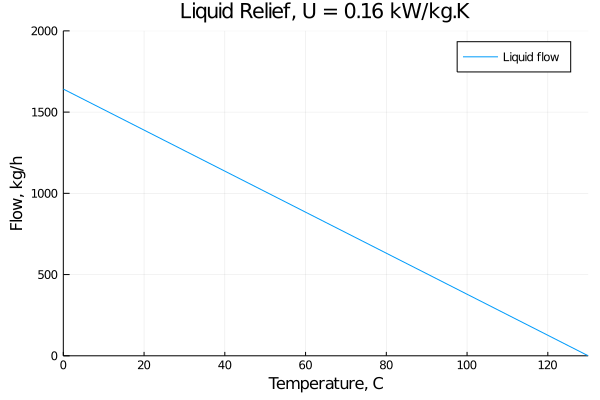
This reasonable estimate for the maximum relief rate, at 0 C initial temperature, is near 1700 kg/h. The value estimated using the simple formula from API 521 gives 4148 kg/h. Lets see what the maximum steam flow would be using this reasonable approximation for the heat transfer process.
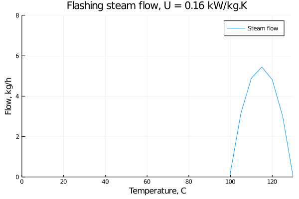
This reasonable esitmate for the maximum steam flow rate is just over 5 kg/h.
Recap
Lets summarize the results.
- Simple method. 4148 kg/h liquid, 234 kg/h steam.
- Design U. Max 25,000 kg/h liquid, 80 kg/h steam.
- Limiting U. Max 1700 kg/h liquid, 5 kg/h steam.
Now we see that the simple calculation method, suggested by API 521, is a reasonble (and hopefully conservative) estimate of the liquid relief rate when the exchanger is cold. The physical justifcation for the simple calculation is a bit thin, but the excessive driving force due to cold liquid is balanced by a much lower heat transfer coefficient.
But if we want more detail, such as that needed to calculate the maximum amount of flashing steam, then we need to use a different strategy. This is where we see that the design U value for the exchanger can be used with our worst-case cold-side temperature, and we get an appropriately conservative result. And we can be confident that there is no way on God’s green earth that this amount of heat can be transferred: we ignored the dominant resistance to heat transfer. This calculation should give a reasonable amount of margin for the assessment of the downstream relief system. And now we can check if a small, simple design is feasible.
Lets use a reasonable amount of design margin on our designs to avoid unnecessary complexity and risk in the facilities that we design.